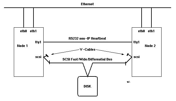


A HA cluster consists of the following components:
There are five basic failover strategies for resource groups in the market, all of which have different names depending on the vendor:
The primary node owns the resource group; the backup node runs idle, only supervising the primary node. In case of a primary node outage, the backup node takes over. The nodes are prioritized, which means the surviving node with the highest priority will acquire the resource group. A higher priority node joining the cluster will thus cause a short service interruption. The nodes can be different in power, the standby node just being powerful enough to ensure degraded operation.
Two nodes as in Idle Standby but without priority. The node which enters the cluster first will own the resource group, and the second will join as a standby node. This failover strategy is especially interesting if the short service interruption caused by a joining higher priority node is unwanted. Rotating resource groups can get quite confusing if more than two nodes are involved, plus the nodes need to be about equivalent in power.
The primary node owns the resource group. The backup node runs a non-critical application (e.g. a web or FTP server, a development or test environment) and will take over the critical resource group but not vice versa. If the backup node isn't powerful enough for running both the business critical resource group and the non-critical application, the latter may be stopped. Upon reintegration of the failed node, the backup machine will release the resources of the business critical application and potentially restart the non-critical load. The reintegrating primary node in turn re-claims the business critical resource group.
This is basically a two-way Idle Standby: two servers are configured so that both can take over the other node's resource group. Both must have enough CPU power to run both applications with sufficient speed -- or performance losses must be taken into account until the failed node reintegrates. This also works nicely in three- or more node configurations.
All nodes run the same resource group (there can be no IP or MAC address in a concurrent resource group!) and access the external storage concurrently. There is currently only one application in the marketplace which makes use of this feature: Oracle Parallel Server. This requires a very efficient concurrent lock manager which may be an option for future extensions. The failover strategy here is basically null: if an application instance fails, the IP address of the failed node may or may not be taken over depending on the clients' intelligence and flexibility.
The application itself is normally not subject to supervision by the
HA software agent. Linux-HA should be completely generic, allowing to
make every application HA that can be run in the background without
operator intervention (e.g. from cron). Optionally, there
could be a clustering API & library as a future extension,
allowing applications to communicate with the HA software agent
easily.
The business critical application's user data must reside on an external storage device which can be taken over by a standby node in case of an outage. This is usually achieved by attaching the storage device in a "twin-tailed" manner (see diagram). Due to length restrictions of the SCSI cabling (25 meters for fast/wide/differential SCSI), multi-host attachments are normally limited to 4 nodes per storage device. The Serial Storage Architecture (SSA) (see section Serial Storage Architecture) supports up to 8 nodes per SSA loop. Both technologies allow for very flexible failover strategies which are also capable of handling multiple points of failure, e.g. multiple standby nodes for a server node, one standby node for multiple server nodes or even multiple standby nodes for multiple server nodes.


